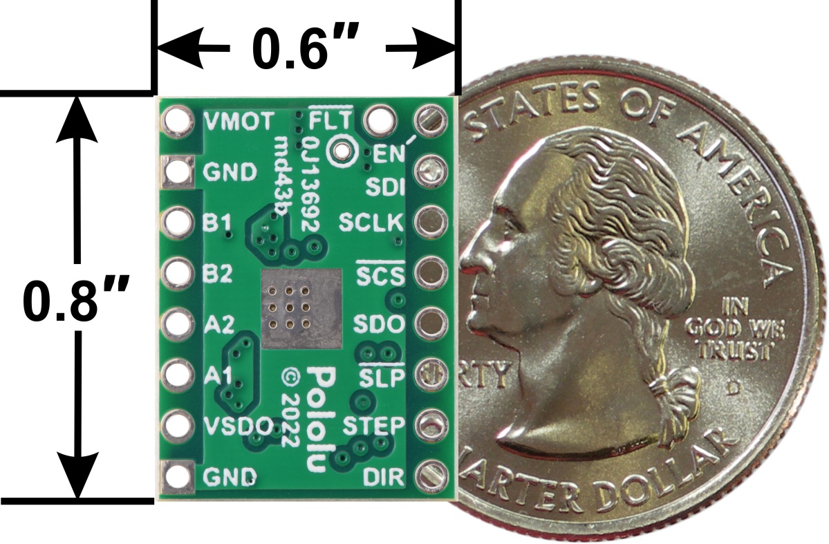
![DRV8434S 4.5-48V(포텐시오미터 조정 최대 2A) 바이폴라 스테퍼 모터 드라이버 모듈 (SPI 전류 제한 설정/핀 헤더 미납땜) [PLLU-3766]](javascript:slideChange('mainImage', '//wy.junui.cn/data/images/goods/23/08/34/1000036309/1000036309_magnify_094.jpg'); "DRV8434S 4.5-48V(포텐시오미터 조정 최대 2A) 바이폴라 스테퍼 모터 드라이버 모듈 (SPI 전류 제한 설정/핀 헤더 미납땜) [PLLU-3766]")
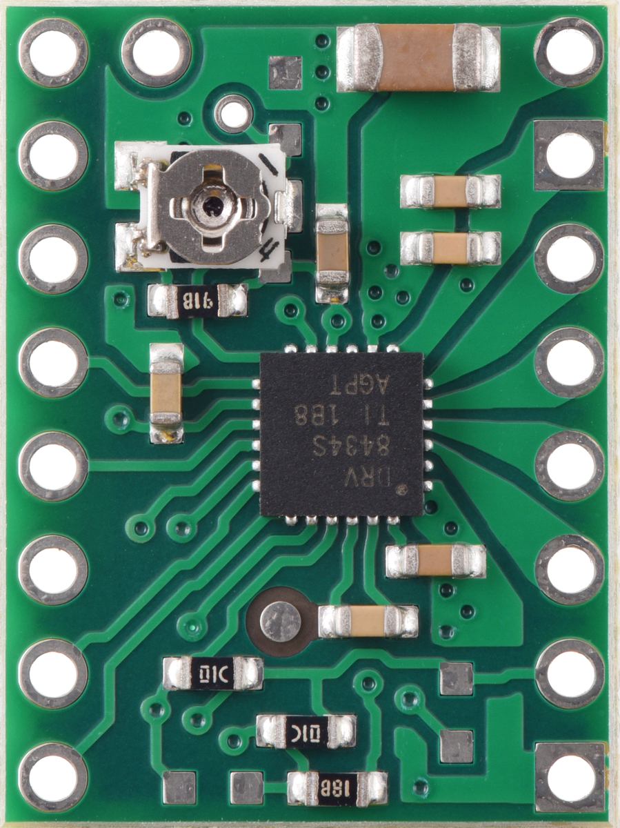
![DRV8434S 4.5-48V(포텐시오미터 조정 최대 2A) 바이폴라 스테퍼 모터 드라이버 모듈 (SPI 전류 제한 설정/핀 헤더 미납땜) [PLLU-3766]](javascript:slideChange('mainImage', '//wy.junui.cn/data/images/goods/23/08/34/1000036309/1000036309_magnify_154.jpg'); "DRV8434S 4.5-48V(포텐시오미터 조정 최대 2A) 바이폴라 스테퍼 모터 드라이버 모듈 (SPI 전류 제한 설정/핀 헤더 미납땜) [PLLU-3766]")
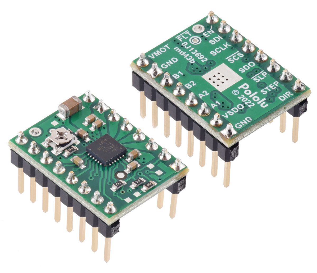
![DRV8434S 4.5-48V(포텐시오미터 조정 최대 2A) 바이폴라 스테퍼 모터 드라이버 모듈 (SPI 전류 제한 설정/핀 헤더 미납땜) [PLLU-3766]](javascript:slideChange('mainImage', '//wy.junui.cn/data/images/goods/23/08/34/1000036309/1000036309_magnify_227.jpg'); "DRV8434S 4.5-48V(포텐시오미터 조정 최대 2A) 바이폴라 스테퍼 모터 드라이버 모듈 (SPI 전류 제한 설정/핀 헤더 미납땜) [PLLU-3766]")
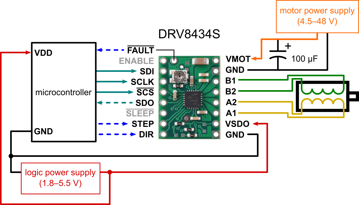
![DRV8434S 4.5-48V(포텐시오미터 조정 최대 2A) 바이폴라 스테퍼 모터 드라이버 모듈 (SPI 전류 제한 설정/핀 헤더 미납땜) [PLLU-3766]](javascript:slideChange('mainImage', '//wy.junui.cn/data/images/goods/23/08/34/1000036309/1000036309_magnify_314.jpg'); "DRV8434S 4.5-48V(포텐시오미터 조정 최대 2A) 바이폴라 스테퍼 모터 드라이버 모듈 (SPI 전류 제한 설정/핀 헤더 미납땜) [PLLU-3766]")
-
 6,051원
-
 14,391원
-
 3,627원
-
 4,680원
-
 2,470원
-
 3,120원
-
 2,860원
-
 7,670원
-
 3,640원
![DRV8434S 4.5-48V(포텐시오미터 조정 최대 2A) 바이폴라 스테퍼 모터 드라이버 모듈 (SPI 전류 제한 설정/핀 헤더 미납땜) [PLLU-3766]](http://wy.junui.cn/data/images/goods/23/08/34/1000036309/1000036309_main_012.jpg "DRV8434S 4.5-48V(포텐시오미터 조정 최대 2A) 바이폴라 스테퍼 모터 드라이버 모듈 (SPI 전류 제한 설정/핀 헤더 미납땜) [PLLU-3766]")
추천 상품


관련 상품
-
6,051원
XLR 암컷(F) to USB-C 변환 케이블 (동적 마이크용 PC-노트북 녹음 케이블) 1M [ZBL034-005]
-
14,391원
ip2368 양방향 고출력 고속 충전 모듈 파워뱅크 회로 기판 세트 PD100W 승강압 고속 충전 [ZTA180-325]
-
3,627원
자동차 오디오 Hi-Low 컨버터 (서브우퍼 오디오 변환기) [ZTP50-092]
-
4,680원
5A 듀얼 채널 DC 모터 드라이버 모듈 리모컨 가능 정역회전 PWM 속도 제어 듀얼 H-브리지 L298N 초월형 5A [ZTH83-011]
-
2,470원
TP353 사각파 출력 NE555 모듈 발진기 가변 주파수 펄스 발생기 신호원 5kHz-250kHz DC 5-15V [ZTX101-179]
-
3,120원
TP353 사각파 출력 NE555 모듈 발진기 가변 주파수 펄스 발생기 신호원 50Hz-6kHz DC 5-15V [ZTX101-178]
-
2,860원
TP353 사각파 출력 NE555 모듈 발진기 가변 주파수 펄스 발생기 신호원 0.5Hz-70Hz DC 5-15V [ZTX101-177]
-
7,670원
12V 4선 PWM 팬 온도 제어 속도 조절기 3A 온도+RPM 디스플레이 팬 속도 소음 감소 및 정지 기능 [ZTJ68-017]
-
3,640원
음성 녹음 모듈 칩 CHR05M 195초 녹음 고음질 초저전력(13μA) 커스텀 가능 [ZTP50-021]
-
 12,090원
51 단일 칩 마이크로컨트롤러 게임 패드 테트리스 키트 재미있는 전자 게임기 DIY 부품 세트 [DIY-344]
12,090원
51 단일 칩 마이크로컨트롤러 게임 패드 테트리스 키트 재미있는 전자 게임기 DIY 부품 세트 [DIY-344]

-
1 XLR 암컷(F) to USB-C 변환 케이블 (동적 마이크용 PC-노트북 녹음 케이블) 1M [ZBL034-005]
6,051 원 -
2 ip2368 양방향 고출력 고속 충전 모듈 파워뱅크 회로 기판 세트 PD100W 승강압 고속 충전 [ZTA180-325]
14,391 원 -
3 자동차 오디오 Hi-Low 컨버터 (서브우퍼 오디오 변환기) [ZTP50-092]
3,627 원 -
4 5A 듀얼 채널 DC 모터 드라이버 모듈 리모컨 가능 정역회전 PWM 속도 제어 듀얼 H-브리지 L298N 초월형 5A [ZTH83-011]
4,680 원 -
5 TP353 사각파 출력 NE555 모듈 발진기 가변 주파수 펄스 발생기 신호원 5kHz-250kHz DC 5-15V [ZTX101-179]
2,470 원


이미지 확대보기 DRV8434S 4.5-48V(포텐시오미터 조정 최대 2A) 바이폴라 스테퍼 모터 드라이버 모듈 (SPI 전류 제한 설정/핀 헤더 미납땜) [PLLU-3766]
![DRV8434S 4.5-48V(포텐시오미터 조정 최대 2A) 바이폴라 스테퍼 모터 드라이버 모듈 (SPI 전류 제한 설정/핀 헤더 미납땜) [PLLU-3766]](javascript:slideChange('magnifyImage .img_photo_big', '//wy.junui.cn/data/images/goods/23/08/34/1000036309/1000036309_magnify_094.jpg'); "DRV8434S 4.5-48V(포텐시오미터 조정 최대 2A) 바이폴라 스테퍼 모터 드라이버 모듈 (SPI 전류 제한 설정/핀 헤더 미납땜) [PLLU-3766]")
![DRV8434S 4.5-48V(포텐시오미터 조정 최대 2A) 바이폴라 스테퍼 모터 드라이버 모듈 (SPI 전류 제한 설정/핀 헤더 미납땜) [PLLU-3766]](javascript:slideChange('magnifyImage .img_photo_big', '//wy.junui.cn/data/images/goods/23/08/34/1000036309/1000036309_magnify_154.jpg'); "DRV8434S 4.5-48V(포텐시오미터 조정 최대 2A) 바이폴라 스테퍼 모터 드라이버 모듈 (SPI 전류 제한 설정/핀 헤더 미납땜) [PLLU-3766]")
![DRV8434S 4.5-48V(포텐시오미터 조정 최대 2A) 바이폴라 스테퍼 모터 드라이버 모듈 (SPI 전류 제한 설정/핀 헤더 미납땜) [PLLU-3766]](javascript:slideChange('magnifyImage .img_photo_big', '//wy.junui.cn/data/images/goods/23/08/34/1000036309/1000036309_magnify_227.jpg'); "DRV8434S 4.5-48V(포텐시오미터 조정 최대 2A) 바이폴라 스테퍼 모터 드라이버 모듈 (SPI 전류 제한 설정/핀 헤더 미납땜) [PLLU-3766]")
![DRV8434S 4.5-48V(포텐시오미터 조정 최대 2A) 바이폴라 스테퍼 모터 드라이버 모듈 (SPI 전류 제한 설정/핀 헤더 미납땜) [PLLU-3766]](javascript:slideChange('magnifyImage .img_photo_big', '//wy.junui.cn/data/images/goods/23/08/34/1000036309/1000036309_magnify_314.jpg'); "DRV8434S 4.5-48V(포텐시오미터 조정 최대 2A) 바이폴라 스테퍼 모터 드라이버 모듈 (SPI 전류 제한 설정/핀 헤더 미납땜) [PLLU-3766]")

장바구니 담기
상품이 장바구니에 담겼습니다.
바로 확인하시겠습니까?
찜 리스트 담기
상품이 찜 리스트에 담겼습니다.
바로 확인하시겠습니까?


- 상호명 : 주식회사 오픈올
- 대표 : 김순복
- 사업자등록번호 : 782-87-01534
- 통신판매업신고번호 : 2022-인천미추홀-1772
- 전화 : 070-5029-4550
- 팩스 : 02-6499-9949
- 주소 : 인천광역시 미추홀구 주염로73번길 54 제이원플렉스 631호
- 개인정보관리자 : 김순복
- 메일 : openidea@openidea.co.kr
copyright (c) www.openidea.co.kr all rights reserved.