![ACS711EX -15.5-+15.5A 0.090V/A 전류 센서 모듈 [PLLU-2452]](javascript:slideChange('mainImage', '/data/images/goods/23/08/34/1000035958/1000035958_magnify_02.jpg'); "ACS711EX -15.5-+15.5A 0.090V/A 전류 센서 모듈 [PLLU-2452]")
![ACS711EX -15.5-+15.5A 0.090V/A 전류 센서 모듈 [PLLU-2452]](javascript:slideChange('mainImage', '/data/images/goods/23/08/34/1000035958/1000035958_magnify_177.jpg'); "ACS711EX -15.5-+15.5A 0.090V/A 전류 센서 모듈 [PLLU-2452]")
![ACS711EX -15.5-+15.5A 0.090V/A 전류 센서 모듈 [PLLU-2452]](javascript:slideChange('mainImage', '/data/images/goods/23/08/34/1000035958/1000035958_magnify_278.jpg'); "ACS711EX -15.5-+15.5A 0.090V/A 전류 센서 모듈 [PLLU-2452]")
-
 20,700원
-
 4,300원
-
 4,000원
-
 3,100원
-
 564,300원
-
 900원
900원
-
 1,400원
-
 13,200원
-
 103,500원
![ACS711EX -15.5-+15.5A 0.090V/A 전류 센서 모듈 [PLLU-2452]](/data/images/goods/23/08/34/1000035958/1000035958_main_049.jpg "ACS711EX -15.5-+15.5A 0.090V/A 전류 센서 모듈 [PLLU-2452]")
추천 상품
관련 상품
-
20,700원
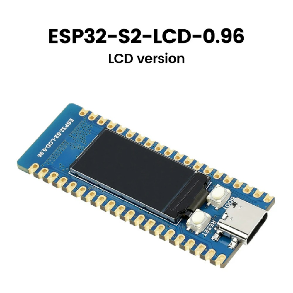
Esp32-S2-LCD-0.96 와이파이 개발 보드 마이크로 컨트롤러 단일 코어 32 비트 0.96 인치 LCD 디스플레이 [OPEN-ZTF111-175]
-
4,300원
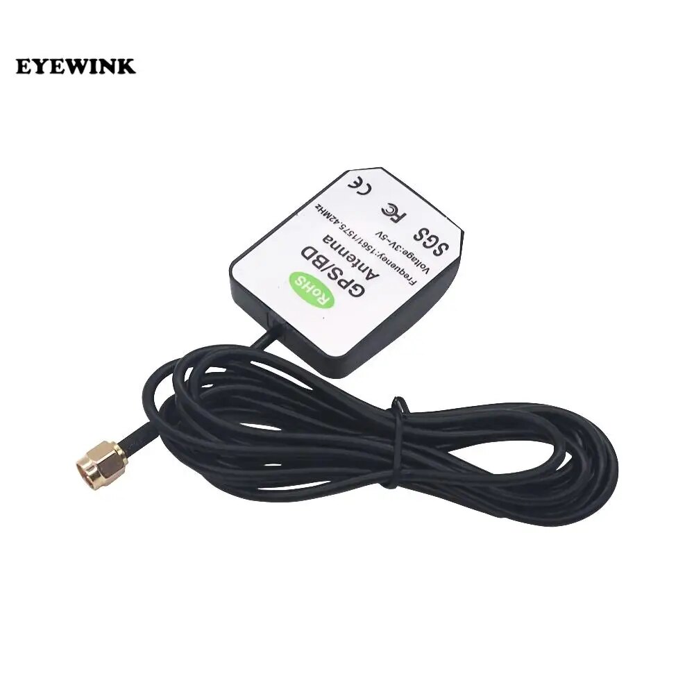
차량용 GPS 안테나 2M GPS 수신기 자동차 DVD 내비게이션 앰프 야간 투시경 카메라 액티브 원격 안테나 공중 어댑터 커넥터 [ZTY11-21]
-
4,000원
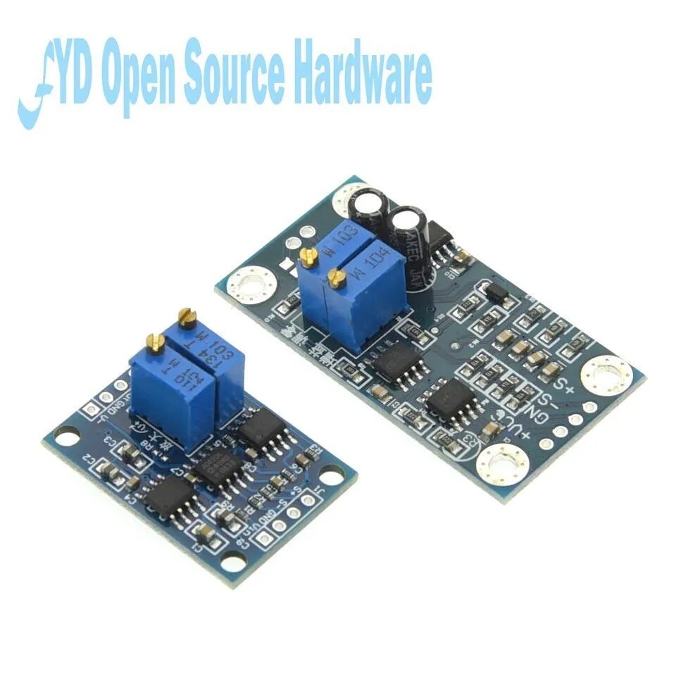
신호 계측 모듈 보드 AD620 마이크로볼트 MV 전압 증폭기 3-12VDC [OPEN-ZTA174-439]
-
3,100원
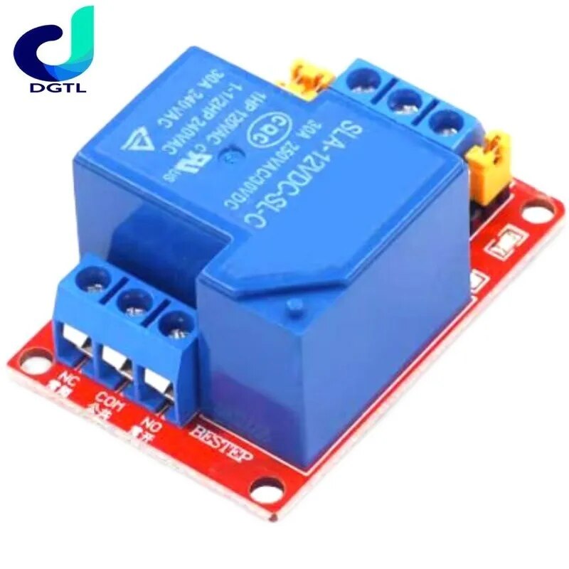
하이 로우 레벨 트리거 1 채널 릴레이 모듈 옵토커플러 절연 보드 모듈 Arduino PIC AVR DSP ARM용 5V 12V 24V 30A [OPEN-ZTD35-85]
-
564,300원
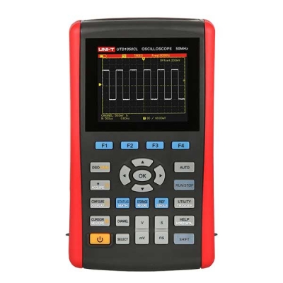
휴대용 디지털 오실로스코프 UTD1050CL
-
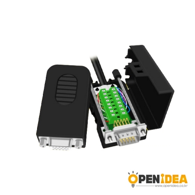
900원
DB15 VGA 젠더 터미널블럭 RS232 [OPEN-CB015-001]
-
1,400원
자동차 휴즈 세트 중형 15A (20개) [OPEN-CM037-007]
-
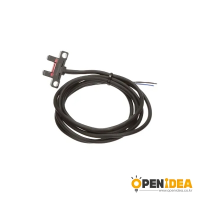
13,200원
PM-K25 PANASONIC 파나소닉 포토센서 [OPEN-HD007-002]
-
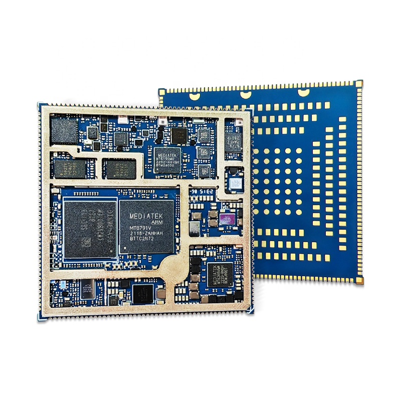
103,500원
MT8791 안드로이드 코어 보드 MediaTek 모바일 보드 안드로이드 마더 보드 사용자 정의 개발 PCB 맞춤형 안드로이드 보드 설계 [NewMobi-08]
-
 483,600원
MT6877 안드로이드 코어 보드 MediaTek 안드로이드 메인보드 개발 보드 5G 모듈 솔루션 개발 [NewMobi-07]
483,600원
MT6877 안드로이드 코어 보드 MediaTek 안드로이드 메인보드 개발 보드 5G 모듈 솔루션 개발 [NewMobi-07]
-
1 Esp32-S2-LCD-0.96 와이파이 개발 보드 마이크로 컨트롤러 단일 코어 32 비트 0.96 인치 LCD 디스플레이 [OPEN-ZTF111-175]
20,700 원 -
2 차량용 GPS 안테나 2M GPS 수신기 자동차 DVD 내비게이션 앰프 야간 투시경 카메라 액티브 원격 안테나 공중 어댑터 커넥터 [ZTY11-21]
4,300 원 -
3 신호 계측 모듈 보드 AD620 마이크로볼트 MV 전압 증폭기 3-12VDC [OPEN-ZTA174-439]
4,000 원 -
4 하이 로우 레벨 트리거 1 채널 릴레이 모듈 옵토커플러 절연 보드 모듈 Arduino PIC AVR DSP ARM용 5V 12V 24V 30A [OPEN-ZTD35-85]
3,100 원 -
5 휴대용 디지털 오실로스코프 UTD1050CL
564,300 원

이미지 확대보기 ACS711EX -15.5-+15.5A 0.090V/A 전류 센서 모듈 [PLLU-2452]
![ACS711EX -15.5-+15.5A 0.090V/A 전류 센서 모듈 [PLLU-2452]](javascript:slideChange('magnifyImage .img_photo_big', '/data/images/goods/23/08/34/1000035958/1000035958_magnify_02.jpg'); "ACS711EX -15.5-+15.5A 0.090V/A 전류 센서 모듈 [PLLU-2452]")
![ACS711EX -15.5-+15.5A 0.090V/A 전류 센서 모듈 [PLLU-2452]](javascript:slideChange('magnifyImage .img_photo_big', '/data/images/goods/23/08/34/1000035958/1000035958_magnify_177.jpg'); "ACS711EX -15.5-+15.5A 0.090V/A 전류 센서 모듈 [PLLU-2452]")
![ACS711EX -15.5-+15.5A 0.090V/A 전류 센서 모듈 [PLLU-2452]](javascript:slideChange('magnifyImage .img_photo_big', '/data/images/goods/23/08/34/1000035958/1000035958_magnify_278.jpg'); "ACS711EX -15.5-+15.5A 0.090V/A 전류 센서 모듈 [PLLU-2452]")

장바구니 담기
상품이 장바구니에 담겼습니다.
바로 확인하시겠습니까?
찜 리스트 담기
상품이 찜 리스트에 담겼습니다.
바로 확인하시겠습니까?


- 상호명 : 주식회사 오픈올
- 대표 : 김순복
- 사업자등록번호 : 782-87-01534
- 통신판매업신고번호 : 2022-인천미추홀-1772
- 전화 : 070-5029-4550
- 팩스 : 02-6499-9949
- 주소 : 인천광역시 미추홀구 주염로73번길 54 제이원플렉스 631호
- 개인정보관리자 : 김순복
- 메일 : openidea@openidea.co.kr
copyright (c) www.openidea.co.kr all rights reserved.